GPR5300 Technical Document
May 2021 (1724 Words, 10 Minutes)
Introduction
This repository contains a simple C++20 OpenGL rendering engine capable of loading .obj(+ it’s .mtl) 3D model files with .ktx textures using etc1 compression. GLSL shaders were used.
External libraries used
All the libraries are linked together using vcpkg and cmake. The basis for the engine and the vcpkg and cmake configurations has been provided by Elias Farhan.
Hardware/Software used
The engine has been made to run reasonably (consistent 60 FPS) on the following platform:
- CPU: i7-6500U @ 2.50[GHz], 2 physical core, 4 logical.
- RAM: 16[GB].
- GPU: Nvidia GeForce 940M with 2[GB] of VRAM, with driver version ~466.47
- Microsoft Windows 10 Home x64, ~version 10.0.19042 .
Techniques used
These are the techniques used in the demo in no particular order:
Instancing
Instancing simply consists in re-using the same per-vertex data to draw multiple instances of a mesh in different places using a single draw call. This is the default behaviour of the engine. The only exception is the drawing of the skybox.
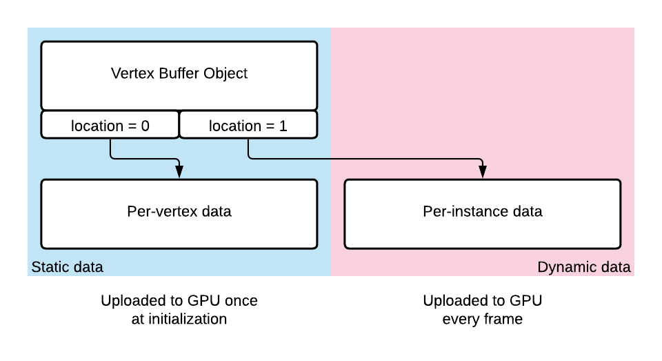
This technique comes in particularly handy for things like particle systems. In this demo, a single particle consists of a mesh of 3 intersecting planes with an alpha texture used to draw the shape of a star on each plane:

This same mesh is simply instanced 512 times in my case: the per-vertex data is loaded into the GPU’s memory once at initialization and the dynamic per-instance data of 3 floats representing the position of the mesh is transfered to the GPU once every frame, resulting in a total transfer of 6’144 bytes. Each particle is then colored in the fragment shader using it’s gl_InstanceId as input to give them differing colors. The vertex shader input ends up therefore looking something like this:
layout (location = 0) in vec3 VertexPosition; // Changes for every vertex.
layout (location = 1) in vec3 ModelPosition; // Changes for every instance.
Frustum culling
Although the scene is simple enough not to warrant an such an optimization, every time a Model is drawn, the user is given the option to perform a culling pass using the camera’s frustum to determine which instances of the Model need to be updated and displayed. In the case of this engine the use of this pass is less to limit the number of draw calls, as with instancing this isn’t an issue, but rather to limit the amount of dynamic data that needs to be transferred to the GPU every frame. This optimization should do little when the number of instances of a Model is small as the most lengthy operation in such a scenario would be the wait on the GPU, but should get more effective as the number of instances grow.
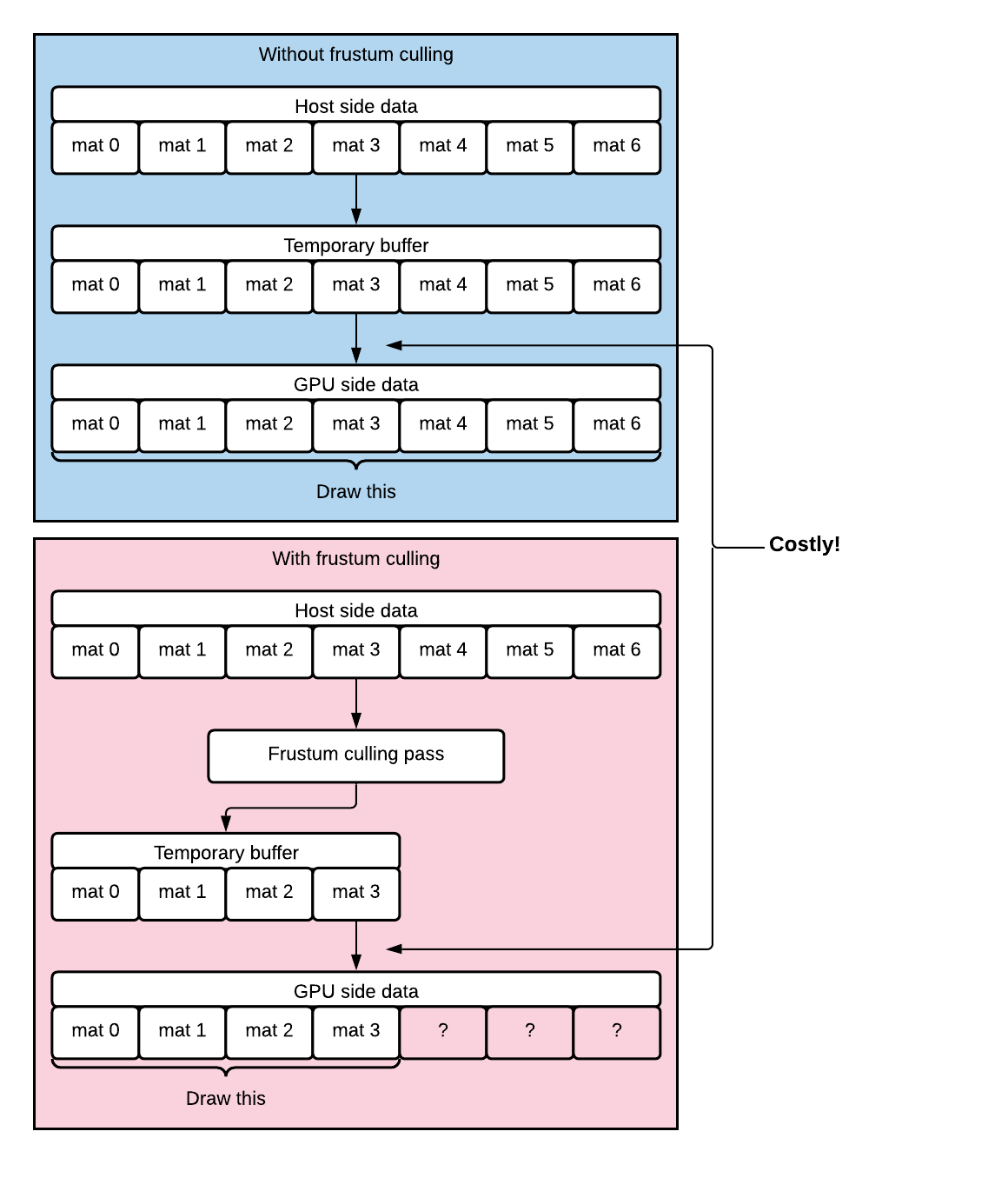
A list of instances to draw can be easily established thusly: only the instances whose position relative to the camera’s position lays inside the camera’s frustum need to be drawn. To know whether an object is within the frustum, all we need to do is examine the geometric projection of the object’s position vector onto the vectors normal to the planes that make up the frustum. This is easilly comprehensible when considering the frustum’s Z axis:
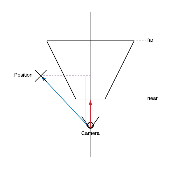
We can see that the object COULD only be within the frustum’s bound only if the projection of the blue vector is greater than the Z coordinate of the near plane AND smaller than the Z coordinate of the far plane. The blue vector is given by: ObjectPosition - CameraPosition. The red vector is the Front vector of the camera. Similarly, the same comparison is to be done for each of the side planes of the frustum:

As you can see, this time if the projection of the blue vector on the red one is greater than zero, there’s no way the object could be inside the frustum. This time, the red vector is given by rotating the camera’s Left vector by FOV/2 degrees counter-clockwise. This can easily be done using glm::angleAxis(radian, axis).
Shape interpolation
Shape interpolation is a very simple technique that allows a shape to be interpolated between two other shapes on the condition that the vertices of the two other shapes have a one-to-one correspondance:
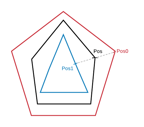
Here, we have two targets. One is a red pentagon with 5 vertices. The other a blue triangle with 5 vertices as well but two of them are located on the triangle’s sides. If we pass these two sets of data to the vertex shader as well as an arbitrary interpolation factor, we can create a third shape, drawn here in black that is a mixture of the pentagram and the triangle.
This was how the roof collapsing effect was done for the Half Life 2’s E3 2003 tech demo.
Normalmapping
All objects in the scene that are shaded using the Blinn-Phong’s lighting model are using a normal map: a texture that instead of colors contains the xyz components of a vector that would be normal to the surface of the object at it’s texture coordinate. Using these normals instead of the ones generated from the .obj’s data gives us a much better resolution of the object’s surface at very little cost.
Deferred shading
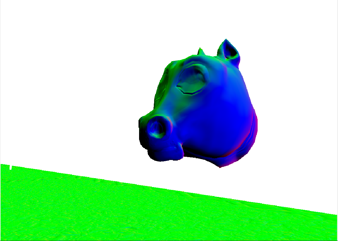
The rendering pass is separated between a geometry pass and a shading pass. The geometry pass gathers all the data relevant for computing the lighting and writes it to 4 separate targets: one for a fragment’s albedo, one for it’s position, one for it’s normal and one for the material’s shininess. The shading pass then takes these inputs as textures and computes the lighting for the whole screen, so no needless lighting computation is performed: all pixels thusly rendered are guaranteed to be the ones displayed on screen.


Bloom effect
During the shading pass, a bloom effect is applied globally to the whole screen. The basic idea behind a bloom effect is simple: in addition to drawing the scene as usual, draw a copy of it onto a second texture but only the pixels that are brighter than some arbitrary value. Blur this second texture and combine it with the first result of the shading pass and you end up with something like this:

The result is that light appears to bleed into it’s surroundings and appears brighter than it actually is. While there’s multiple ways to implement this effect, the differences lay in the way this second texture that only contains the bright colors is blurred. Some might perform the blurring effect per fragment, others write the texture back and forth between two framebuffers that reduce in size to then upscale the minified texture, or it is even possible to simply sample the unblurred texture from a smaller mipmap with the proper filtering parameters to obtain a blurring effect. In this engine’s case, the method is very simple: During the post-processing pass, once all the shading has been performed once per pixel during the deferred shading pass, a simple mean blur is applied to the brights texture and then added to the post-process pass’ result before tone mapping and gamma correction.
void main()
{
    vec3 result = MeanBlur();
    result = ExtendedReinhard(result, MaxBrightness);
    result = pow(result, vec3(1.0/GAMMA));
    FragColor = vec4(result, 1.0);
}
This gives satisfying results and simply adds a small extra step into the existing rendering pipeline without the need to switch render targets, without generating mipmaps and without performing the blur on a per-fragment basis, everything written to the brights texture will be used for the final result.
Shadow mapping
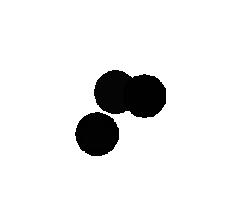
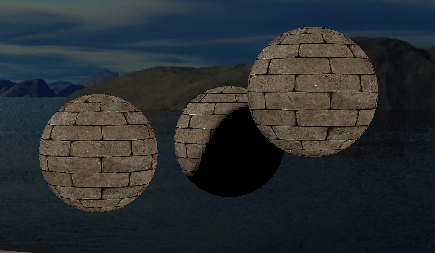
This demo also has three brick textured spheres that cast shadows on each other. To achieve this, a simple shadow map for a directional light was used. The idea is simple: draw the scene once before the lighting pass and keep only the depth values but with the scene seen from the directional light’s point of view. Once at the shading stage, compare the pixel’s current depth value with the one stored in the shadow map. If the fragment’s current depth as seen from the light’s perspective is greater than the one that is stored in the depth map at the same location, it means that the current fragment is in shadow.
The Demo
A .zip package is provided in the release section of the repository containing a standalone demo that uses the rendering engine to showcase a simple scene.
The demo’s layout
Once the demo is launched, the camera automatically moves along the world’s Z axis in the -Z direction. The camera rotates to show each of the 5 elements in the scene as the scene progresses. The whole demo lasts ~55 seconds and then resets.
1. The morphing horse
A disembodied horse’s head is shown to transition between it’s default aspect and a “spherifyed” version of the mesh:
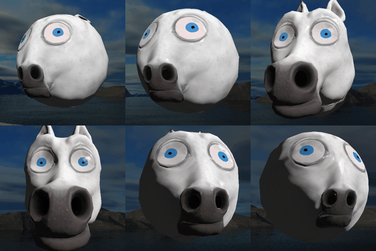
This is a demonstration of shape interpolation, a very simple technique where the values of a vertex are interpolated between two shapes with the exact same amount of vertices. The vertex shader simply interpolated between the two vertices to obtain the final vertex:
in vec3 Position0;
in vec3 Position1;
uniform float factor;
void main()
{
  gl_Position = vec4(mix(Position0, Position1, factor), 1.0);
}
2. The particle system
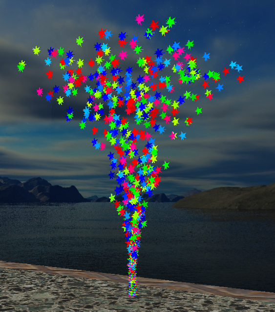
A bunch of stars are shown to fly up into the air in a “trumpet” like shape:
This is done with some simple instancing and trigonometric functions. Each particle’s position is updated every frame and the buffer containing the positions of all the particles is sent over to the GPU once per frame. An instancing command is then issued and the particles are drawn using the new positions.
3. The reflective diamond
A spinning diamond is shown to reflect the skybox. The reflected color is boosted to make the diamond appear brighter and cause some blooming effect when the bright sky is reflected.
The reflection is done via the use of glsl’s built-in reflect function, the resulting reflection vector being used to sample the skybox’s cubemap.

4. The shadow casting spheres
Three orbiting spheres are shown to cast shadows on each other as they orbit:
This is done via shadowmapping.

5. The normalmapped cube
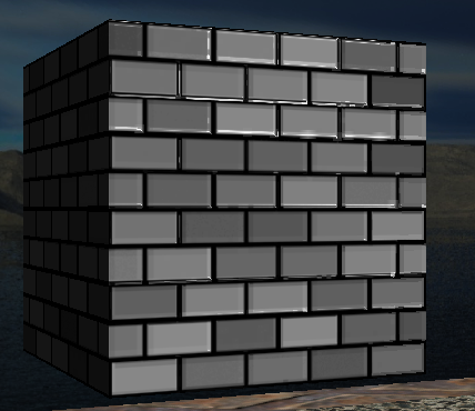
A brick textured cube is shown to reflect light according to a geometry that is more complex than that contained in it’s .obj file:
This is done via simple normalmapping.
The demo’s execution flow
The high level view of the program’s flow is as such:
